
O General AC Error Codes & Troubleshooting Guide [Finder Tool]
O General AC showing an error code? Find out what it means with our error code finder and learn how to fix it using our simple troubleshooting guide.
TL;DR – Key Takeaways
O General inverter split ACs don’t show error codes on a digital display. Instead, they signal faults through blinking patterns on the Operation, Timer, and Economy LEDs. Learning to decode these O General AC error codes is the first step toward understanding what’s wrong with your unit. Some faults are minor and clear up with a simple power reset, while others point to a deeper issue that needs professional attention.
This guide gives you a quick-reference error code table, step-by-step instructions for reading the LED blink pattern, and cause-by-cause troubleshooting for the most common faults. It also explains clearly when the problem is safe to check yourself and when you should call a trained technician instead.

O General AC error code lookup
Type your error code below to see what it means and the quick fix to try.
O General AC Error Codes List
Match your LED blink count to the table below to identify your error instantly.
| LED Pattern (Operation-Timer) | Error Code (Wired RC) | What It Means | Quick Fix |
|---|---|---|---|
| 1-1 | 11 | Serial communication error | Reset power, check wiring |
| 1-2 | 12 | Wired RC communication error | Check remote wiring |
| 1-4 | 14 | Network communication error | Check network wiring |
| 1-5 | 15 | Check run unfinished | Run test cycle again |
| 1-6 | 16 | Transmission/peripheral connect error | Check connector, cabling |
| 2-1 | 21 | Refrigerant circuit address error | Call technician – address setup |
| 2-2 | 22 | Indoor unit capacity error | Call technician – check settings |
| 2-3 | 23 | Combination error | Verify indoor-outdoor match |
| 2-4 | 24 | Connection unit number error | Check unit connections |
| 2-6 | 26 | Address setting error | Recheck address setting |
| 2-7 | 27 | Master/slave unit set-up error | Reconfigure unit setup |
| 2-9 | 29 | IU connection error on WRC | Check wired remote link |
| 3-1 | 31 | Power supply interruption error | Check incoming power supply |
| 3-2 | 32 | Indoor PCB EEPROM error | Call technician – PCB fault |
| 3-5 | 35 | Manual auto switch error | Call technician – switch check |
| 3-10 | 3A | Indoor unit WRC communication error | Check wired remote cable |
| 4-1 | 41 | Inlet air temp sensor error | Check sensor, wiring |
| 4-2 | 42 | Indoor Heat-Ex middle temp sensor error | Check coil sensor wiring |
| 5-1 | 51 | Indoor unit fan motor error | Clean fan, check motor |
| 5-2 | 52 | Indoor EEV error | Call technician – valve fault |
| 5-3 | 53 | Drain pump error | Clear drain, check float switch |
| 5-7 | 57 | Damper error | Check swing motor, linkage |
| 5-8 | 58 | Intake grille error | Check grille closure |
| 5-15 | 5U | Indoor unit error | Call technician for diagnosis |
| 6-2 | 62 | Outdoor PCB communication error | Reset power, check wiring |
| 6-3 | 63 | Inverter error | Call technician – inverter fault |
| 6-4 | 64 | Active filter/PFC circuit error | Call technician – PCB fault |
| 6-5 | 65 | Trip terminal “L” error | Check power, wiring trip |
| 6-10 | 6A | Display PCB communication error | Check display cable |
| 7-1 | 71 | OU discharge temp sensor error | Check sensor, wiring |
| 7-2 | 72 | Compressor temp sensor error | Check sensor, wiring |
| 7-3 | 73 | OU Heat-Ex liquid temp sensor error | Check sensor, wiring |
| 7-4 | 74 | OU ambient temp sensor error | Check sensor, wiring |
| 7-5 | 75 | OU suction refrigerant temp sensor error | Check sensor, wiring |
| 7-6 | 76 | 2/3-way valve temp sensor error | Check valve sensor |
| 7-7 | 77 | OU heat sink temp sensor error | Clean heat sink, check sensor |
| 8-2 | 82 | Sub-cool inlet/outlet temp sensor error | Check sensor, wiring |
| 8-3 | 83 | OU liquid pipe temp sensor error | Check sensor, wiring |
| 8-4 | 84 | OU current sensor error | Call technician – sensor check |
| 8-6 | 86 | HP/LP pressure sensor/switch error | Call technician – pressure check |
| 9-4 | 94 | OU current trip detection | Check compressor load |
| 9-5 | 95 | Compressor rotor position error | Call technician – compressor |
| 9-7 | 97 | OU fan motor error | Check outdoor fan, wiring |
| 9-8 | 98 | OU fan motor 2 error | Check outdoor fan, wiring |
| 9-9 | 99 | 4-way valve error | Call technician – valve fault |
| 9-10 | 9A | Coil (expansion valve) error | Call technician – valve check |
| 9-15 | 9U | Outdoor unit error | Call technician for diagnosis |
| 10-1 | A1 | OU abnormal discharge temp error | Check refrigerant, airflow |
| 10-3 | A3 | Abnormal compressor temp error | Call technician – compressor |
| 10-4 | A4 | High pressure error | Clean coil, check airflow |
| 10-5 | A5 | Low pressure error | Check refrigerant, filters |
| 13-1 | J1 | VRF branch box error | Call technician – branch box |
| 13-2 | J2 | 3-way multi branch box error | Call technician – branch box |

Hire Our Expert Blue Star AC Technician in Kolkata Without Advance Charges
How to Read O General AC LED Error Codes?
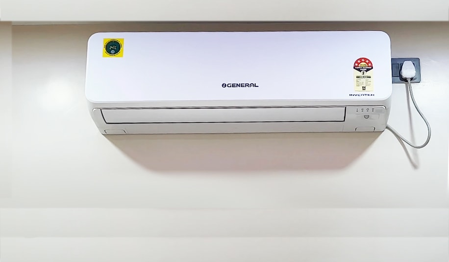
O General inverter ACs use three indoor LEDs to signal faults: Operation (Green), Timer (Orange), and Economy/Powerful (Green). The Operation LED represents the first digit of the error code, and the Timer LED represents the second digit. Count the number of flashes on each LED before the sequence repeats to get your two-digit code.
For example, if the Operation LED flashes 2 times and the Timer LED flashes 3 times, the error is 2-3, which points to an indoor pipe or coil temperature sensor error.
Follow these steps to read the code correctly:
- Observe the Operation LED and count the flashes.
- Observe the Timer LED and count the flashes.
- Check whether the Economy LED stays continuously lit, which confirms fault mode.
- Match the two-digit combination to the error table in Section 2.
Before You Start Troubleshooting (Checklist)
Note: This reset step alone resolves many temporary faults caused by voltage fluctuation.
If you are not confident anough for fixing the O General AC errors by yourself, immidiately contact Urban Service Plaza, the best O General AC service centre in Kolkata & nearby areas for out of warranty AC. No advance booking charges & 15 days service guarantee.
Troubleshoot Common O General AC Error Codes
Serial Communication Error (Code 11 / 1-1)
Possible Causes:
- This error means the indoor and outdoor units cannot communicate with each other, which stops the AC from functioning normally. It usually happens because the signal between the two units gets interrupted somewhere along the wiring path.
- The most common triggers are broken or loose communication wiring, an incorrect wiring sequence, or a PCB failure on either the indoor or outdoor unit. Even a single loose terminal can be enough to break the entire communication link.
What to Check:
- Check the communication cable for continuity and inspect all terminal connections for looseness or corrosion. A weak or broken connection at any point in the cable run can trigger this fault.
- Measure the supply voltage and check the status of both PCBs. If the wiring tests fine, the problem likely lies with one of the circuit boards.
- For low cost inverter and non-inverter AC PCB repair service call us at +919831015086
Indoor Room Temperature Sensor Error (Code 2-2)
Symptoms: Operation LED = 2 flashes, Timer LED = 2 flashes.
Possible Causes:
- The room temperature sensor may have developed an open circuit or a short circuit, which prevents it from sending accurate readings to the PCB. This sensor plays a key role in regulating cooling, so any fault here disrupts normal operation.
- A loose sensor connector or a damaged sensor wire can also cause the same error, even if the sensor itself is in working condition.
What to Check:
- Inspect the sensor wiring carefully and check that the connector is firmly seated on the indoor PCB. Loose or corroded connections are a frequent cause of this fault.
- Measure the sensor’s resistance and compare it with the expected value. Replace the sensor if the reading falls outside the normal range.
Indoor Pipe/Coil Temperature Sensor Error (Code 2-3)
Symptoms: Operation = 2 flashes, Timer = 3 flashes.
Possible Causes:
- This error points to the coil sensor mounted on the evaporator pipe, which may be open, shorted, or have a loose connector or damaged wire. Since this sensor tracks coil temperature, a fault here can affect cooling performance and trigger repeated errors.
What to Check:
- Inspect the sensor mounted on the evaporator pipe and check its resistance against the manufacturer’s specification. Make sure it is properly clipped onto the pipe and not just loosely resting near it.
- Replace the sensor if it tests defective, since a damaged coil sensor rarely repairs itself and will keep triggering the same code.
Timer LED Blinking Alone (2 Times vs 3 Times)
Possible Causes (2 blinks):
- A standalone 2-blink pattern on the Timer LED usually points to a communication failure between the indoor and outdoor units, separate from the full 1-1 serial error.
Possible Causes (3 blinks):
- A 3-blink pattern usually suggests an indoor PCB relay problem, an outdoor PCB fault, or low and fluctuating supply voltage. Voltage instability is a common trigger, especially in areas with frequent power fluctuations.
What to Check:
- Check the communication cable and all terminals for looseness, since a poor connection is often the simplest explanation for this pattern.
- Measure the incoming voltage and the PCB output voltage, then repair or replace the faulty PCB if the wiring and voltage both test normal.
Indoor Fan Motor Error (Code 51)
Possible Causes:
- This error can result from indoor blower motor failure, a jammed fan, or ice accumulation on the coil that stops the fan from spinning freely. Any of these can prevent the blower from delivering normal airflow.
- A dirty evaporator, low refrigerant, or a fan motor driver fault can also trigger this code, since restricted airflow puts extra strain on the motor.
What to Check:
- Verify that the blower rotates freely and inspect the motor connector for looseness or damage. A blower that resists turning by hand usually points to a mechanical or electrical fault.
- Defrost and clean the evaporator coil, then check the refrigerant pressure. Clearing ice and dirt often resolves the issue if the motor itself tests fine.
Outdoor Fan Motor Error (9-7/97)
Possible Causes:
- This error is usually caused by motor failure, a physical obstruction blocking the fan blades, or a fault in the PCB driver responsible for controlling fan speed.
What to Check:
- Check that the fan rotates freely by hand, inspect the capacitor if the unit uses one, and test the outdoor PCB. Debris or bent blades around the outdoor unit are common and easy-to-fix causes.
Compressor Rotor Position Detection Error (9-5/95)
Possible Causes:
- This fault typically occurs when the compressor is locked, the IPM or inverter has failed, or the system cannot correctly detect the compressor rotor’s position during startup. It is considered a more serious electrical fault than a simple sensor issue.
What to Check:
- Measure the compressor winding resistance and insulation values, then inspect the inverter PCB for visible damage. Because this involves high-voltage components, this check is best left to a trained technician.
Compressor Temperature Sensor Error (7-2/72)
Possible Causes:
- A faulty thermistor, a loose connector, or a damaged wire near the compressor can all trigger this error. Since this sensor protects the compressor from overheating, the fault code appears even for minor wiring issues.
What to Check:
- Test the sensor resistance, inspect the wiring for damage, and check the PCB connector for a secure fit. Replace the sensor only after confirming the wiring and connector are not the actual cause.
Outdoor Discharge Temperature Error (10-1/A1)
Possible Causes:
- Refrigerant shortage, a blocked or dirty condenser, or a faulty discharge sensor can all cause this error. Reduced airflow or low refrigerant makes the compressor run hotter than normal, which the sensor then flags.
What to Check:
- Clean the condenser coil, verify the refrigerant charge against the specified level, and measure the discharge sensor’s output. Addressing airflow and refrigerant issues often resolves the fault without needing a sensor replacement.
High Pressure Error (10-4/A4)
Possible Causes:
- A dirty condenser, outdoor fan failure, refrigerant overcharge, or restricted airflow around the outdoor unit can all push system pressure above safe limits. This is a protective error meant to prevent damage to the compressor.
What to Check:
- Clean the condenser coil, check that the outdoor fan is working properly, and verify the refrigerant charge is correct. Make sure nothing is blocking airflow around the outdoor unit before assuming a component has failed.
Low Pressure Error (10-5/A5)
Possible Causes:
- A refrigerant leak, a faulty expansion valve, or restricted indoor airflow can all cause system pressure to drop below the safe operating range.
What to Check:
- Perform leak detection, measure the refrigerant pressure, and inspect the indoor airflow path for blockages. A confirmed leak will need proper repair and refrigerant recharge rather than a simple top-up.
Contact us for a gas leakage inspection and AC refrigerant gas filling service in Kolkata at affordable cost.
Current Sensor Error (Code 84)
Possible Causes:
- This error usually points to a failed current sensor, a defect on the PCB, or a wiring issue affecting the current measurement circuit.
What to Check:
- Test the current sensor and inspect the PCB for visible damage or loose connections. Since this involves precise electrical measurement, verifying with a multimeter is recommended before replacing any part.
Inverter Error (Code 63)
Possible Causes:
- An inverter PCB failure, a compressor problem, or a power supply issue can all trigger this fault. Since the inverter controls compressor speed, any fault here directly affects cooling performance.
What to Check:
- Measure the DC bus voltage, test the IPM module, and check the compressor windings for resistance and insulation faults. This is a component-level fault that generally requires a technician’s diagnostic equipment.
Indoor PCB EEPROM Error (Code 32)
Possible Causes:
- This error indicates a memory failure on the indoor PCB, meaning the stored settings or configuration data can no longer be read correctly.
What to Do:
- Replace or repair the indoor PCB, since a corrupted EEPROM cannot usually be fixed through a simple reset or wiring check.
Drain Pump Error (Code 53)
Possible Causes:
- Pump failure, an activated float switch, or a blocked drain line can all cause this error. The float switch is designed to trigger when water cannot drain properly, so a blockage is often the simplest explanation.
What to Check:
- Check the pump’s operation, inspect the drain hose for clogs, and test the float switch. Clearing a blocked drain hose often resolves the error without needing to replace the pump.
Damper Error (Code 57)
Possible Causes:
- A swing motor failure or a physical obstruction blocking the damper’s movement can trigger this fault. The damper controls airflow direction, so any resistance to its movement is picked up as an error.
What to Check:
- Inspect the swing motor and the linkages connecting it to the damper. Removing any obstruction blocking the damper’s path is often enough to clear the fault.
Outdoor Communication Error (Code 62)
Possible Causes:
- A PCB communication failure or a wiring issue between the indoor and outdoor units can cause this error. It is closely related to the general serial communication fault but specifically points to the outdoor side of the link.
What to Check:
- Check the communication cable, then inspect both the indoor and outdoor PCBs. As with most communication errors, a loose or damaged wire is usually the first thing to rule out.
Signs You Need Professional AC Repair Help
Some O General error codes are not DIY-friendly. If the fault involves PCB failure, inverter or IPM faults, compressor rotor issues, or the same code returns even after a power reset, it needs a certified technician rather than a home fix. Attempting repairs on these components without proper training risks further damage or injury.
Call a technician if:
Urban Service Plaza, an ISO 9001:2015 certified organization, offers doorstep AC repair service across Kolkata and nearby areas, backed by a network of certified in-house technicians.
Key Takeaways
Most O General error codes trace back to loose wiring, dirty coils, voltage instability, or sensor faults, not always a major breakdown. Power-cycling the unit first remains the fastest way to clear temporary faults before deeper troubleshooting.
However, codes involving the PCB, inverter, or compressor need professional diagnosis to avoid further damage. Urban Service Plaza offers doorstep AC repair service across Kolkata for such cases.


