Call Technician

Carrier AC Error Code List & Troubleshooting [Checklist]
Look up Carrier AC error codes instantly and get quick fixes. Trusted AC repair service now available in Kolkata by Urban Service Plaza.
TL;DR:
Modern Carrier air conditioners use LED blink patterns or digital display codes to flag specific faults inside the unit. These Carrier AC error codes act as a diagnostic language, pointing directly to the part or sensor causing trouble. Understanding them helps you decide the right next step quickly.
The same code can mean different things across window, split, inverter, and VRF models. This guide gives you an instant code lookup table, causes and fixes for common errors, and clear advice on when a DIY check is safe versus when to call a technician.

Carrier AC Error Code Lookup Table (Instant Reference)
Use this table to quickly find your Carrier AC error code, understand what it means, and see the recommended quick solution.
Carrier AC error code lookup
Type your error code below to see what it means and the quick fix to try.
| Error Code | Meaning | Quick Solution |
|---|---|---|
| E0/EH00 | Indoor EEPROM parameter error | Reset power 5-10 min; reprogram or replace indoor PCB if it persists |
| E1/EH01 | Indoor/outdoor communication error | Check communication wiring and connectors; verify power supply |
| E2 | Zero-crossing detection / power supply error | Verify voltage; check plug and PCB connections |
| E3 | Indoor fan speed out of control | Check fan motor, capacitor, and blower for obstruction |
| E4 | Room/outdoor ambient temperature sensor error | Inspect sensor wiring and resistance; replace if faulty |
| E5 | Evaporator coil sensor error | Check sensor resistance and connector; replace if defective |
| E6 | Indoor evaporator coil / communication error | Check sensor and indoor PCB |
| E7 | Outdoor coil temperature sensor / PCB communication error | Inspect sensor placement and wiring |
| E9 | Cold blow protection (heating mode) | Usually not a fault; normal protection function |
| EC | Refrigerant leakage detected | Stop use; call technician for leak test and recharge |
| ACL | Filter cleaning reminder | Clean filters and reset reminder |
| F0 | Low refrigerant / outdoor AC current protection | Check refrigerant pressure and current draw |
| F1 | Outdoor ambient temperature sensor open/short | Check sensor resistance and wiring |
| F2 | Condenser coil temperature sensor error | Check sensor resistance and wiring |
| F3 | Compressor discharge temperature sensor error | Check sensor and compressor cooling |
| F4 | Outdoor EEPROM parameter fault | Reset power; replace outdoor PCB if persistent |
| F5 | Outdoor fan motor/speed fault | Check fan motor rotation and wiring |
| F8 | Compressor suction temperature sensor fault | Check sensor resistance |
| P0 | IPM/IGBT malfunction | Requires technician inspection of inverter module |
| P1 | Over-voltage/under-voltage protection | Check mains voltage; install stabilizer if fluctuating |
| P2 | Compressor/IPM overheat protection | Clean condenser; check outdoor fan |
| P4 | Compressor starting/out-of-step abnormal | Check compressor windings and inverter PCB |
| P5 | Compressor phase current protection | Check compressor current draw |
| P6 | Outdoor DC voltage protection | Check inverter drive and PCB communication |
| P7 | IPM temperature overheat protection | Clean unit; check heat sink sensor |
| P8 | Compressor discharge overheat protection | Check refrigerant and condenser cooling |
| P9 | Indoor anti-freezing protection | Check airflow, filter, and refrigerant level |
| L1/L2 | Drive bus voltage over/under protection | Check mains voltage stability |
| L3/L4 | Drive phase current overload/sampling fault | Requires technician inspection |
| L9/LC/LD/LE/LF | Compressor voltage, startup, phase, stalling, overspeed faults | Requires technician diagnosis |
| U1 | Compressor phase detection malfunction | Requires technician inspection |
| U3 | Low DC bus voltage | Check mains voltage supply |
| DN | Communication error between PCB and EXV | Check wiring; requires technician |
| A5/A7 | Condenser sensor / mode conflict error | Check sensor and settings |
| C5 | Jumper missing on replacement indoor PCB | Install jumper per service manual (technician task) |
| 13-57 series | Multi-split indoor sensor/communication/freeze/mode errors | See Section 7 table |

Hire Our Expert Carrier AC Technician for Same Day Home Service in Kolkata
How to Read Carrier AC Error Codes (LED Flash Codes vs Digital Display)?
Older and non-inverter Carrier AC models, including many window units, do not show text. Instead, they communicate faults through LED blink counts. For example, E0 flashes 25 times, while F4 flashes only once.
Split and inverter Carrier ACs work differently. These models typically show the alphanumeric code directly on the indoor unit’s digital display.
Steps to read a flash code:
- Count the total blinks in one repeating cycle.
- Note any pause pattern between blink groups.
- Match the flash count to the code table above.
Flash-count mapping and code meaning can differ by exact model. Always check the service manual for your specific model when possible.
Urban Service Plaza offers reliable, out-of-warranty Carrier AC repair in Kolkata. Not an authorized centre, but we use genuine spare parts and back every repair with a bill and guarantee.
Carrier AC Error Codes Explained in Detail (Causes & Fixes)
E0/EH00 – Indoor EEPROM Parameter Error
Possible Causes:
- Indoor unit EEPROM parameter error means the indoor PCB’s memory chip has lost or corrupted its stored settings. This can happen after a power surge or PCB aging.
- A faulty indoor PCB can also trigger this fault directly. The memory chip itself may be damaged.
What to Do:
- Reset power for 5-10 minutes to allow the PCB to reinitialize. This clears many temporary EEPROM glitches.
- If the code persists, the indoor PCB may need reprogramming or replacement. This is best handled by a technician.
E1/EH01 – Indoor/Outdoor Communication Error
Possible Causes:
- Indoor PCB failure can stop the unit from sending or receiving signals correctly. This often shows up as a complete communication breakdown between units.
- A communication wiring fault between the indoor and outdoor units is a common trigger. Damaged or loose wires disrupt the signal path.
- Missing or incorrect power supply can also set off this code. The system needs stable voltage to communicate properly.
What to Do:
- Verify that a 220-230V power supply is present and steady. Unstable power often causes false communication errors.
- Check communication wiring for damage or looseness at both ends. Reconnect or replace any worn sections.
- Inspect indoor PCB output using a multimeter. Replace the PCB if it shows no proper signal output.
E2 – Zero-Crossing Detection / Power Supply Error
Possible Causes:
- Low or unstable voltage disrupts the AC’s internal zero-crossing detection. This can trigger the error even when other parts work fine.
- Loose wiring connections at the plug or PCB level are a frequent cause. They create intermittent power loss.
- Indoor coil freezing due to restricted airflow can also set off this code, especially in dusty or blocked units.
What to Do:
- Verify supply voltage stability using a meter over a few minutes. Fluctuations point to an external power issue.
- Check the plug, cable, and PCB connections for looseness. Tighten or replace any damaged parts.
- Inspect evaporator airflow and the temperature sensor if the coil is freezing. Clean the filter first, since blocked airflow is the usual root cause.
E3 – Indoor Fan Speed Out of Control
Possible Causes:
- A seized fan motor or winding failure stops the fan from spinning within its normal speed range. This is one of the most common causes of this code.
- PCB output failure means the board isn’t sending the right signal to the fan motor. The motor itself may be fine.
- Low refrigerant pressure can also trigger this fault in some models, even when the fan is mechanically sound.
What to Do:
- Rotate the fan manually to check for obstruction or stiffness. It should turn freely without resistance.
- Measure motor winding resistance with a multimeter. Compare the reading against the manufacturer’s specification.
- Check refrigerant pressure if fan checks come back normal. A technician can confirm this with gauges.
E4 – Room/Outdoor Ambient Temperature Sensor Error
Possible Causes:
- A sensor open circuit or short circuit prevents accurate temperature readings. This confuses the AC’s control logic.
- A loose sensor connector is a simple but common cause. It can disconnect during regular vibration or servicing.
- Compressor overheating is a more serious cause, often linked to poor cooling or blocked airflow around the outdoor unit.
What to Do:
- Inspect sensor placement and wiring carefully. Make sure it sits correctly in its designated slot.
- Measure sensor resistance with a multimeter and replace it if the reading falls outside the normal range.
- Check compressor cooling and surrounding airflow. Clear any blockage around the outdoor unit.
E5 – Evaporator Coil Sensor Error
Possible Causes:
- A faulty sensor is the most direct cause of this error. It fails to send accurate readings to the control board.
- A loose connector or open/short circuit in the sensor wiring can also produce this fault.
What to Do:
- Verify sensor resistance with a multimeter against the expected value. This confirms whether the sensor itself is faulty.
- Inspect wiring and ensure correct sensor placement inside the unit. Misplaced sensors give false readings.
- Replace the sensor if resistance is abnormal. This usually resolves the error immediately.
E6 – Indoor Evaporator Coil / Communication Error
Possible Causes:
- Coil sensor failure prevents the system from reading evaporator temperature correctly. This is often the first thing to check.
- Loose wiring or a communication fault between boards can also produce this code. Indoor PCB failure is a less common but possible cause.
If you are not confident anough for fixing the Carrier AC by yourself, immidiately contact us for prompt AC repair service in Kolkata & nearby areas without any advance booking charges.
What to Do:
- Check sensor resistance and verify the connector is firmly seated. A loose connection often mimics a sensor failure.
- Replace the sensor if it tests faulty. If the sensor is normal, the indoor PCB likely needs replacement.
E7 – Outdoor Coil Temperature Sensor / PCB Communication Error
Possible Causes:
- A faulty condenser coil sensor is the most common cause of this code. It fails to relay accurate temperature data.
- A loose connection or an outdoor PCB fault can also be responsible, especially in older units.
What to Do:
- Verify sensor placement and measure its resistance with a multimeter. Compare readings against the specification.
- Inspect wiring for damage along the full run. Replace the sensor or PCB if either tests faulty.
E9 – Cold Blow Protection
Possible Causes:
- This code indicates a cold air prevention function that activates during heating mode. It is a built-in safety feature, not a component failure.
What to Do:
- In most cases, no repair is needed since this is usually not a fault. Let the unit complete its normal heating cycle.
- If the code appears outside heating mode or persists unusually long, have a technician check the system.
EC – Refrigerant Leakage Detected
Possible Causes:
- A refrigerant leak, overcharge, or undercharge disrupts the pressure balance the system needs to cool properly.
- Abnormal suction or discharge pressure often accompanies these refrigerant issues and confirms the fault.
What to Do:
- Do not keep running the unit repeatedly to test the leak. This can worsen the problem and strain the compressor.
- Book a professional leak test and pressure check as soon as possible. This pinpoints the exact source of the leak.
- Have refrigerant recovered and recharged to the correct level by a technician. Adding gas without fixing the leak is not a lasting solution.
ACL – Filter Cleaning Reminder
Possible Causes:
- This is not a fault but a scheduled maintenance reminder. It appears after a set number of running hours to prompt filter cleaning.
What to Do:
- Clean the indoor air filters thoroughly to restore proper airflow. Dirty filters reduce cooling efficiency over time.
- Reset the filter reminder after cleaning, following the model’s reset procedure in the user manual.
F0 – Low Refrigerant / Outdoor AC Current Protection
Possible Causes:
- Low refrigerant charge reduces cooling capacity and can trigger this protection code. A refrigeration system blockage can cause the same symptom.
- Outdoor AC current protection activates when the compressor draws excessive current, often due to electrical strain. Contact Urban Service Plaza for same day AC gas filling service.
What to Do:
- Check refrigerant pressure using gauges to confirm the charge level. Low readings point to a leak or undercharge.
- Check current draw at the outdoor unit. A technician should investigate any blockage or electrical irregularity.
F1 – Outdoor Ambient Temperature Sensor Open/Short
Possible Causes:
- The outdoor ambient temperature sensor can develop an open or short circuit over time. This is often due to wear or moisture exposure.
- An inter-unit coil sensor connector defect is possible on some models, producing the same code.
What to Do:
- Check sensor resistance with a multimeter and compare it to the expected value. An abnormal reading confirms a faulty sensor.
- Inspect wiring for corrosion or looseness. Replace the sensor if testing confirms it is defective.
F2 – Condenser Coil Temperature Sensor Error
Possible Causes:
- An open circuit in the condenser coil temperature sensor is the primary cause. It stops the board from reading coil temperature correctly.
- Wiring damage near the sensor can also produce this fault.
What to Do:
- Check sensor resistance and wiring carefully for any visible damage. This narrows down whether the sensor or the wiring is at fault.
- Replace the sensor if its resistance falls outside the normal range specified for the model.
F3 – Compressor Discharge Temperature Sensor Error
Possible Causes:
- A faulty compressor discharge temperature sensor prevents accurate monitoring of discharge heat. This can also appear as an outdoor ambient sensor malfunction on some models.
- Poor compressor cooling can contribute to abnormal readings even when the sensor itself works.
What to Do:
- Check the sensor’s resistance and inspect its wiring for damage. Confirm it matches manufacturer specifications.
- Check compressor cooling and surrounding airflow. Clear any obstruction near the outdoor unit.
F4 – Outdoor EEPROM Parameter Fault
Possible Causes:
- The outdoor unit’s EEPROM parameter fault happens when its memory chip loses stored configuration data. Power surges are a frequent trigger.
- A failing outdoor PCB can also be the underlying cause.
What to Do:
- Reset power to allow the outdoor PCB to reinitialize its memory. This resolves many minor EEPROM issues.
- If the fault persists after a reset, the outdoor PCB likely needs replacement by a technician.
F5 – Outdoor Fan Motor/Speed Fault
Possible Causes:
- Outdoor fan speed running out of control usually points to a fan motor problem. This can include winding failure or a seized motor.
- A discharge temperature sensor malfunction is possible on some models and can produce a similar code.
What to Do:
- Check fan motor rotation manually and inspect the wiring for damage. The motor should spin freely without resistance.
- Measure motor winding resistance and replace the motor if it fails the test.
F8 – Compressor Suction Temperature Sensor Fault
Possible Causes:
- A faulty compressor suction temperature sensor is the direct cause of this code. It fails to provide accurate readings to the control system.
What to Do:
- Check sensor resistance with a multimeter and compare the reading to the expected specification.
- Replace the sensor if it tests outside the normal range. Confirm wiring is intact before replacement.
P0 – IPM/IGBT Malfunction
Possible Causes:
- An IPM (IGBT) module fault indicates a failure in the outdoor unit’s power module. This is a critical electrical component controlling the compressor.
What to Do:
- This fault requires technician inspection of the inverter module. Testing needs specialized equipment and electrical safety precautions.
- Do not attempt to diagnose or replace the IPM module without professional training.
P1 – Over-Voltage/Under-Voltage Protection
Possible Causes:
- Outdoor over-high or over-low AC voltage protection triggers when incoming power falls outside the safe operating range. Unstable local power supply is a common cause.
What to Do:
- Check mains voltage using a meter to confirm it falls within the normal range for the unit.
- Install a voltage stabilizer if the supply fluctuates often. This protects the compressor and PCB long-term.
P2 – Compressor/IPM Overheat Protection
Possible Causes:
- Compressor shell temperature overheat protection activates when the compressor runs too hot. Poor outdoor airflow or a dirty condenser often causes this.
What to Do:
- Clean the condenser coil to restore proper heat exchange. Dust and debris buildup are common culprits.
- Check outdoor fan operation to confirm it is moving air effectively across the coil.
P4 – Compressor Starting/Out-of-Step Abnormal
Possible Causes:
- Compressor starting abnormal can result from phase failure or reversed wiring. Compressor out-of-step abnormal points to the compressor losing synchronization during operation.
What to Do:
- Check compressor windings for continuity and correct resistance. This confirms whether the compressor itself is healthy.
- Inspect the inverter PCB, since it controls compressor timing and startup sequence.
P5 – Compressor Phase Current Protection
Possible Causes:
- This protection triggers when the compressor draws current outside its safe operating range. It often points to an electrical or mechanical strain on the compressor.
What to Do:
- Check compressor current draw using a clamp meter to confirm abnormal readings.
- Have a technician inspect the compressor windings and inverter PCB if current levels are confirmed abnormal.
P6 – Outdoor DC Voltage Protection
Possible Causes:
- Outdoor over-high or over-low DC voltage protection activates when the inverter drive’s internal voltage moves outside safe limits. This can stem from PCB communication issues.
What to Do:
- Check the inverter drive and PCB communication for faults. This requires testing the connection between boards.
- Have a technician verify voltage levels internally, since DC-side issues need specialized tools.
P7 – IPM Temperature Overheat Protection
Possible Causes:
- IPM temperature overheat protection triggers when the inverter power module runs too hot. Poor cooling or a blocked heat sink is a common cause.
What to Do:
- Clean the outdoor unit thoroughly to improve airflow around the module. Dust buildup restricts cooling.
- Check the heat sink sensor to confirm it is reading temperature correctly.
P8 – Compressor Discharge Overheat Protection
Possible Causes:
- Compressor discharge temperature overheat protection activates when discharge gas temperature rises too high. This often links to poor condenser cooling or refrigerant issues.
What to Do:
- Check refrigerant levels and condenser cooling to rule out common causes. Low refrigerant often raises discharge temperature.
- Have a technician verify pressures if refrigerant and airflow both check out normal.
P9 – Indoor Anti-Freezing Protection
Possible Causes:
- Cooling indoor unit anti-freezing protection triggers when the evaporator coil risks icing over. Restricted airflow or a dirty filter is the most common cause.
What to Do:
- Check airflow and clean the filter first, since blocked airflow is the usual root cause of freezing.
- Check refrigerant level if airflow is normal, since low refrigerant can also cause the coil to freeze.
L1/L2 – Drive Bus Voltage Over/Under Protection
Possible Causes:
- Drive bus voltage overload protection and drive bus voltage over-low protection both point to unstable internal voltage on the inverter’s power bus. This often stems from mains supply issues.
What to Do:
- Check mains voltage stability with a meter over a few minutes to identify fluctuations.
- Have a technician inspect the inverter drive circuit if mains voltage tests normal but the code persists.
L3/L4 – Drive Phase Current Overload/Sampling Fault
Possible Causes:
- Drive phase current overload fault happens when the inverter detects excessive current on a phase. Phase current sampling fault points to a problem with the current-sensing circuit itself.
What to Do:
- This fault requires technician inspection, since it involves internal inverter drive electronics.
- Do not attempt to test or reset this code without proper diagnostic equipment.
L9/LC/LD/LE/LF – Compressor Voltage, Startup, Phase, Stalling, Overspeed Faults
Possible Causes:
- These codes cover a range of compressor-related faults, including high voltage conditions, startup failure, phase loss, stalling, and overspeed operation.
What to Do:
- Requires technician diagnosis, since these faults involve compressor electrical testing and inverter drive analysis.
- Do not attempt to restart the unit repeatedly, as this can cause further compressor damage.
U1 – Compressor Phase Detection Malfunction
Possible Causes:
- This code points to a fault in the circuit that detects compressor phase current. It affects the system’s ability to monitor compressor operation correctly.
What to Do:
- Requires technician inspection of the current sensing circuit and inverter PCB.
- Avoid running the unit repeatedly until the fault is diagnosed professionally.
U3 – Low DC Bus Voltage
Possible Causes:
- Low DC bus voltage indicates the inverter’s internal power supply has dropped below its required level. This can stem from mains supply problems or internal component wear.
What to Do:
- Check mains voltage supply to rule out an external cause first.
- Have a technician inspect the DC bus circuit if mains voltage is confirmed stable.
DN – Communication Error Between PCB and EXV
Possible Causes:
- This code signals a communication breakdown between the main PCB and the Electronic Expansion Valve (EXV), which controls refrigerant flow.
What to Do:
- Check wiring between the PCB and EXV for damage or looseness.
- This fault requires a technician, since EXV diagnosis involves refrigerant system expertise.
A5/A7 – Condenser Sensor / Mode Conflict Error
Possible Causes:
- A5 points to a condenser coil inlet temperature sensor malfunction. A7 usually indicates a mode conflict, though it can also signal a condenser outlet sensor issue depending on the model.
What to Do:
- Check the relevant sensor and its wiring if A5 appears. Resistance testing confirms whether replacement is needed.
- Check system settings for conflicting mode commands if A7 appears, especially on multi-unit systems.
C5 – Jumper Missing on Replacement Indoor PCB
Possible Causes:
- A replacement indoor PCB was installed without the required jumper setting. This is common after a recent repair or part swap.
What to Do:
- This is a technician-only fix that requires the model-specific service manual. The correct jumper position varies by model.
- Do not attempt to modify PCB jumpers without proper guidance. Incorrect settings can cause further faults or damage.
13-57 Series – Multi-Split Indoor Sensor/Communication/Freeze/Mode Errors
Possible Causes:
- These codes apply to multi-split systems with several indoor units (A-E). Each unit reports faults using a shifted number range, covering pipe outlet, pipe inlet, return air, mode conflict, and freeze protection issues.
What to Do:
Most of these faults need a technician, since multi-split wiring and sensor layouts are more complex than single-unit systems.
Match the exact code to the correct indoor unit and fault type using the multi-split reference table.
Multi-Split / VRF Carrier AC Error Codes
Carrier multi-split systems connect several indoor units (labeled A, B, C, D, E) to one outdoor unit. Each indoor unit reports faults using a shifted number range, so the same fault type appears as a different code on each unit.
| Code Range | Affected Component | Meaning |
|---|---|---|
| 13/23/33/43/53 | Indoor Units A-E | Indoor pipe outlet temperature sensor malfunction |
| 14/24/34/44/54 | Indoor Units A-E | Indoor pipe inlet temperature sensor malfunction |
| 15/25/35/45/55 | Indoor Units A-E | Indoor return air temperature sensor malfunction |
| 16/26/36/46/56 | Indoor Units A-E | Mode conflict between units |
| 17/27/37/47/57 | Indoor Units A-E | Freeze protection triggered |
| 41/51 | Indoor Unit | Communication error |
| 42/52 | Indoor Unit | Return/mid-pipe temperature sensor malfunction |
Which Carrier AC Errors You Can Try Fixing Yourself vs. Which Need a Technician?
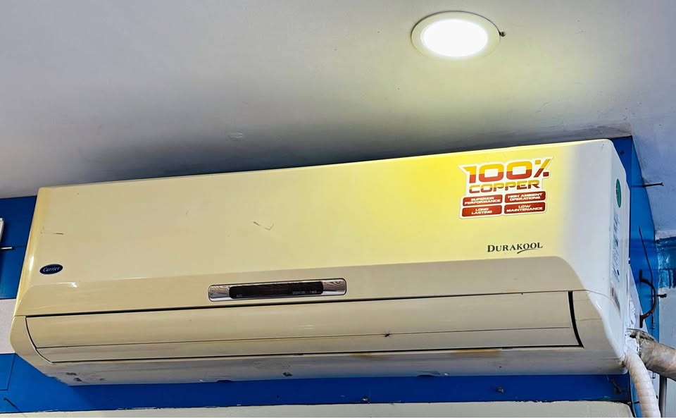
Some Carrier AC errors are safe to check on your own, while others need professional attention. Use this table to decide your next step.
| Safe DIY Checks | Call-a-Technician Situations |
|---|---|
| Power reset for 5-10 minutes on sensor/communication codes (E1, E2, E4, E5) | Refrigerant leak errors (EC), which need leak detection and recharge |
| Cleaning filters and checking for the ACL reminder | Compressor protection codes (P-series, L-series), which need electrical diagnosis |
| Checking wiring/connectors are visibly secure (power off first) | PCB replacement or jumper settings (C5, F4) |
| Verifying stable voltage supply | Repeated tripping or burning smell; stop use immediately |
To Sum Up
Most Carrier AC error codes point to sensor, communication, or power issues. A short reset or basic wiring check can sometimes resolve these without extra help. However, refrigerant leaks, compressor faults, and PCB-jumper errors always need a certified technician.
Don’t ignore a recurring code, since doing so can lead to bigger repair costs later. For reliable, doorstep Carrier AC error diagnosis and repair in Kolkata, Urban Service Plaza offers prompt, professional service you can trust.


![Gree AC Error Codes & Troubleshooting Guide [Error Finder Tool]](https://urbanserviceplaza.co.in/wp-content/uploads/2026/07/gree-ac-error-codes-1-768x432.png)